Non-Essential Essentials: 3D-Print Edition

This section highlights a collection of CAD-designed + 3D-printed creations I built using my Bambu Lab P2S printer. These aren’t items you need, but they’re small conveniences that make everyday tasks easier, and they showcase my approach to turning ideas into functional, well-designed products.
CarryCoaster
Overview
CarryCoaster is a 3D-printed coaster that turns into a one-handed drink carrier using a rotating handle. The idea came from everyday annoyances with standard drinkware, whether its mugs that don’t fit your hand comfortably, handles that force you into an awkward grip, cups that are too hot or slippery to hold, and how easy it is to spill a drink just from moving around.
Rather than relying on a fixed mug handle, CarryCoaster lets you carry a drink from the base, keeping it upright and secure without touching the cup itself. When you’re done carrying it, the handle folds down and it works like a normal coaster, keeping the design simple, compact, and practical for everyday use.


Force & Physics
The cup sits in a circular tray with a cork pad on the bottom. The cork creates strong friction, which keeps the cup from sliding. The cup pushes downward with its weight N = m*g, and the cork can provide a friction force of Ff = μ*N. When you walk or swing the handle, the cup feels a sideways force because you’re moving it around. That sideways force is basically Fside = m*a, where a is the sideways acceleration from your motion. The cup won’t slide as long as Fside < Ffriction. Because the cork has a high friction coefficient and the cup has enough weight, this inequality is almost always satisfied, even when the drink is swung gently in an arc. The small lip around the tray also helps keep the cup centered if it tilts or shifts slightly. Essentially, the cup’s weight pushes down, the cork grips it, and the friction force is stronger than the sideways force from walking or swinging, so the cup stays put.
Materials/Functional Choices
-
Adhesive cork pad: Adds friction to prevent sliding; absorbs condensation
-
Neodymium magnets: Create a smooth, aligned snap when the handle folds down
-
PLA body: Lightweight, rigid, and easy to print

Dog Bowl Splash Guard

Overview
This project started when a friend mentioned her older dog was a notoriously messy eater, constantly splashing water and food behind the bowl. She had been stuffing paper towels behind it as a makeshift barrier. It's effective, but not exactly elegant.
I saw an opportunity to turn a small everyday annoyance into a clean, purposeful product: a custom-fit 3D-printed splash guard that snaps securely onto the dog’s bowl and prevents spills from reaching the wall.
It’s the perfect example of what I call a Non-Essential Essential, just something you technically don’t need, but once it exists, it makes everyday life noticeably easier.
My Role
I designed the entire part from scratch, including:
-
Concept development
-
Precise measurement translation
-
CAD modeling in SolidWorks
-
Mechanism design for the snap-fit
-
Creating a smooth, ergonomic profile
-
Preparing the model for manufacturing via FDM 3D printing

Engineering & Design Process

1. Measuring the Problem
The bowl’s outer diameter includes the rolled stainless-steel rim was 7.625 inches with a rim height of 0.0625 inches. These numbers nearly dictated every dimension of the guard’s internal geometry.
2. Snap-Fit Mechanism
The guard attaches using a controlled interference fit around the bowl’s rim.
Key engineered features:
-
Lip height: 0.05" which captures most of the rim’s height without restricting removal
-
Interference radius: ~3.80–3.82" which creates a gentle snap onto a 3.8125" rim
-
Chamfered underside: ensures smooth attachment without scraping
This gives the perfect balance between tight enough to stay on and loose enough for daily use.
3. Ergonomic Curvature
The body is built using a 180° revolved profile that:
-
Redirects splashes downward
-
Provides structural stiffness
-
Looks clean and intentionally designed
-
Prints easily in one piece
Bag Clip
Overview
This project is a reusable bag clip with an integrated pour spout, designed to make everyday dry goods easier to store and pour. It was created to solve a simple but recurring problem: pouring from flexible bags without a funnel almost always leads to spills. Instead of grabbing another tool or transferring contents into a new container, this design turns the bag itself into a controlled pouring system.
The clip installs directly onto the bag and stays there permanently, allowing the contents to be poured cleanly, resealed tightly, and stored without additional accessories. It’s a small upgrade to an everyday action that removes friction from the process entirely.

Design & Functionality

1. Integrated Pour Spout
A circular pourer is inserted directly into the bag, creating a rigid opening that guides contents cleanly into a container. This eliminates the need for a separate funnel and prevents spills caused by collapsing bags.
2. Threaded Compression System
Both sides of the clip screw together through the bag material, sandwiching it securely between the two components. This creates a tight seal around the pour opening without adhesives or permanent modifications.
3. Revolving Clencher for Tension Control
A rotating clenching mechanism allows the user to tighten the assembly gradually, applying even pressure around the bag opening to keep contents secure and prevent leaks.
4. Sealing Cap for Freshness
A threaded cover screws onto the pour spout to fully close the opening when not in use, helping protect contents from air exposure and spoilage.
5. Reusable & Bag-Agnostic
The design works with a variety of flexible packaging sizes and materials, allowing the clip to be reused across different products rather than being tied to a single bag type.
6. 3D-Print Optimized Components
Threads, tolerances, and wall thicknesses were designed specifically for reliable 3D printing, ensuring smooth assembly and durability without post-processing.
Why it's a Non-Essential Essential
This product isn’t something most people realize they need. It's not until they’ve spilled coffee grounds, protein powder, or grains one too many times. It doesn’t replace the bag or the container, and it doesn’t add complexity to storage. Instead, it quietly removes an annoyance by integrating multiple functions into one object: clipping, sealing, and pouring.

Flower Pen

Overview
This project started as a personal gift for my girlfriend, someone who inspires much of my creativity. I wanted to make something that felt thoughtful and meaningful, but also genuinely useful in her everyday life. I designed a set of flower pens that work as a desk artifact, a daily-use pen, and a bookmark, all in one. When not in use, the flowers sit in a small pot as a decorative piece. When needed, each flower doubles as a removable cap that closes the pen, turning it into a fully functional writing tool.
Design & Functionality
Each component: the flower petals, pistil, stem, leaves, and pot were CAD-designed and 3D-printed as separate parts before final assembly. The pistil locks into the flower head to form a snug pen cap, while the stem houses a Pilot G2 pen refill, requiring careful internal tolerancing to ensure a secure fit without rattling or sliding during use.
The additional leaves stored in the pot introduce a third function: they can be removed and used as bookmarks, adding another layer of everyday utility beyond the pen itself.


Engineering Considerations
-
Internal stem geometry was tuned to fit standard Pilot G2 refills securely
-
Press-fit and slip-fit tolerances were tested to balance ease of assembly with long-term durability
-
Modular part design allowed for iterative testing and reprints without redesigning the full assembly
This project reflects my approach to product design, combining personal intent, thoughtful usability, and practical engineering to turn a simple idea into a functional, well-designed object.
Gaming/Remote Tower
Overview
This project is a modular controller and remote stand designed to organize everyday gaming accessories in a compact, vertical footprint. While not something you need, it solves a small but persistent problem: controllers and remotes constantly being left on tables, couches, or scattered around the room. The goal was to create a single, clean home for multiple devices that feels intentional rather than bulky or overdesigned.
The entire stand was CAD-designed and 3D-printed with a focus on symmetry, balance, and ease of access. By stacking devices vertically and evenly distributing weight around a central column, the stand stays stable while keeping each controller easy to grab and return. It’s meant to quietly blend into a living space while making everyday use more convenient.

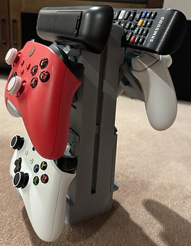


Functional Design Choices
1. Foldable Flaps for Space Saving
The support flaps can fold closed when not in use, allowing the stand to shrink down and reduce its overall footprint. This makes the design adaptable to different setups and prevents unused arms from sticking out unnecessarily.
2. Adjustable Angled Support Arms
Each arm includes multiple slot positions that allow the user to choose between 30°, 45°, or 60° angles. This lets users customize how their controllers rest based on preference, controller shape, or available space.
3. Universal Compatibility
The geometry was intentionally designed to accommodate different controller and remote shapes rather than being locked to a single console or device type.
4. Balanced Weight Distribution
Devices are positioned evenly around the center column, helping the stand remain stable even when only a few controllers are mounted.
5. 3D-Print Optimized Geometry
Wall thicknesses, fillets, and overhangs were designed to print cleanly with minimal supports, making the stand efficient to produce and easy to iterate on.
This design fits within the Non-Essential Essentials category. It’s a small quality-of-life improvement that brings order to something most people already own, without demanding attention or extra space.